At a high level, the 3D printing process includes slicing a CAD file into discrete layers and then building that part layer by layer. In the FFF process, this happens by precisely extruding 3D printing materials in discrete tool paths that trace the outside of a layer and its celled infill.
The specifics of the format of the printer—its construction, what it’s made of, and the quality of its components— factor in to the quality and scale of the parts it can produce.
The parts of a 3D printer
While FDM printers vary in size, materials, and function, they almost all have three distinct electromechanical systems. The function of these systems dictates your print quality.
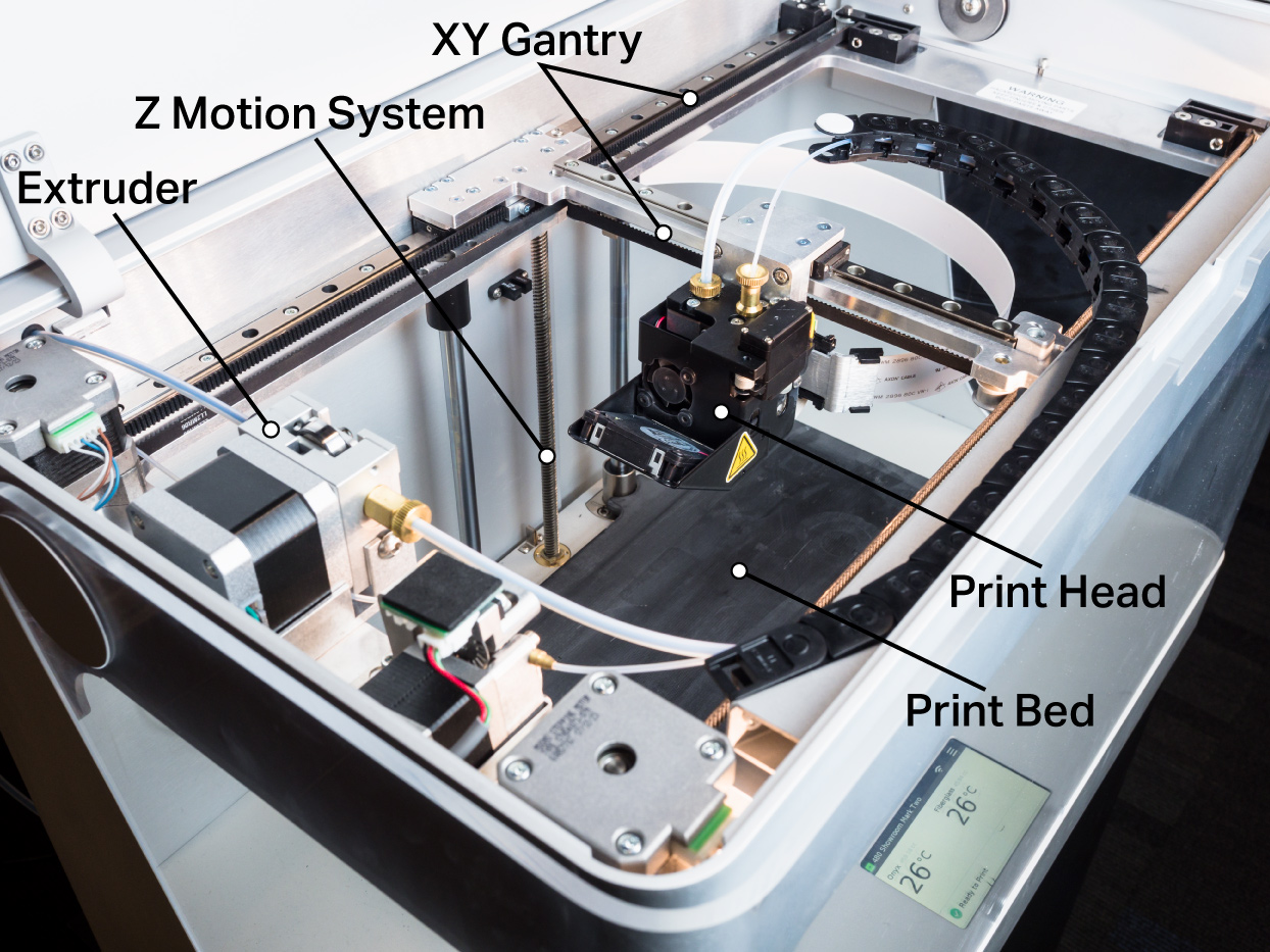
Print head and extrusion system: The system responsible for heating and extruding the thermoplastic print material through a nozzle to form the part. Factors like nozzle size and extrusion speed impact the level of detail the printer can achieve, as well as its print speed.
Print bed and Z motion system: The print head and extrusion system deposits material onto the print bed. As a part prints, the Z motion system moves the bed in discrete, equal steps to form the layers of the part. The precision of the motors driving the Z motion system control the resolution and quality of the part as it is built up in the Z direction.
XY gantry motion system: The print gantry directly controls the X and Y motion of the print head. It’s responsible for “drawing” the tool paths that create each layer. The rigidity of this gantry and the quality of the motors and sensors controlling it impact the precision and accuracy of a part in plane with the print bed.
How a part is built
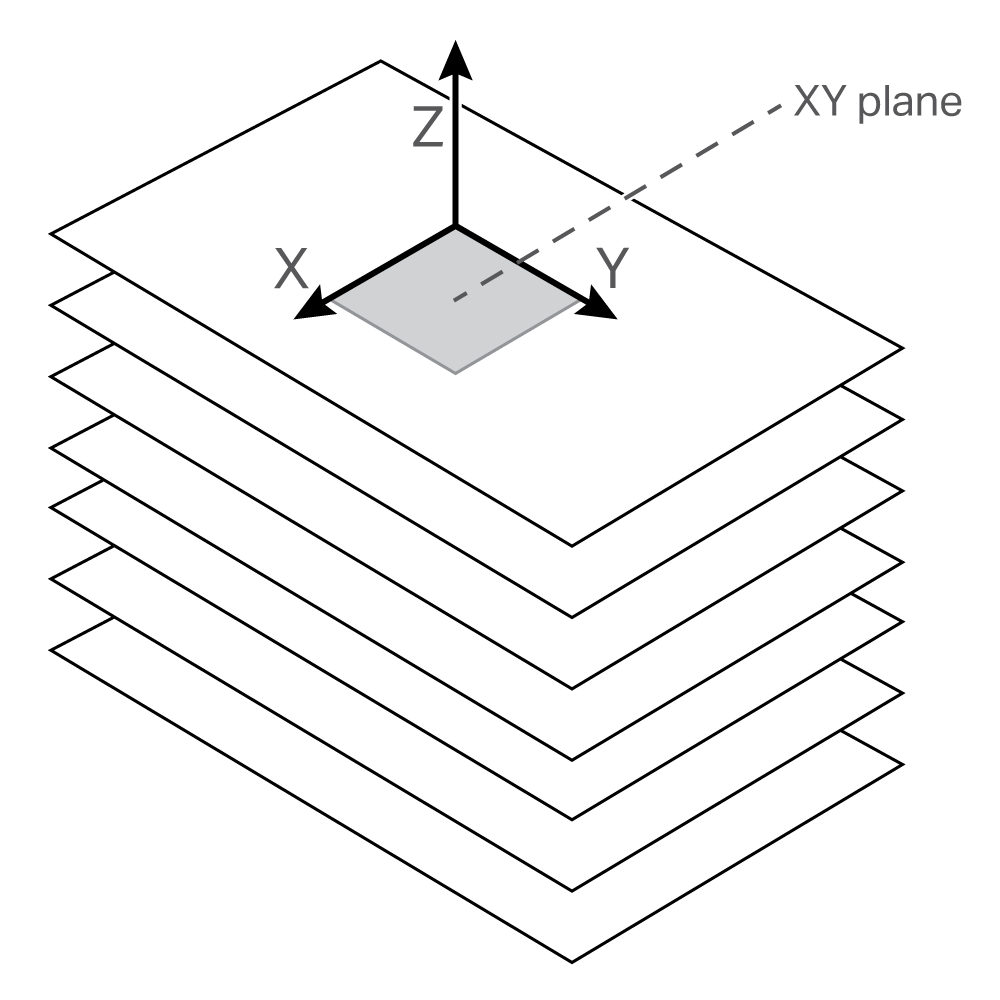
An FFF 3D printer builds its parts in discrete slices called layers. As discussed in our 3D printing software overview, a 3D printing slicer takes an STL file, divides it into layers, then calculates and creates a tool path for each layer. At the beginning of each layer, the print bed is set at a given height and the gantry motion system moves the print head along the tool path as the extrusion system deposits material.
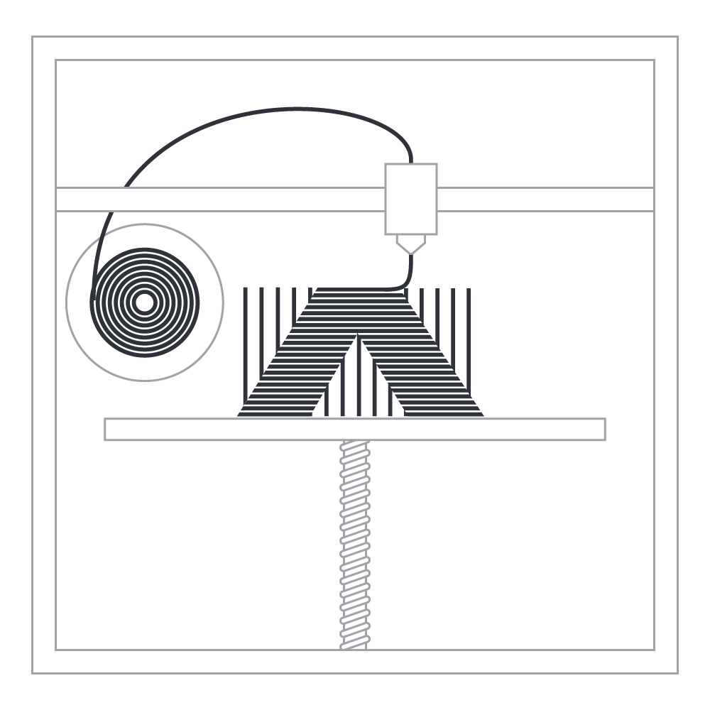
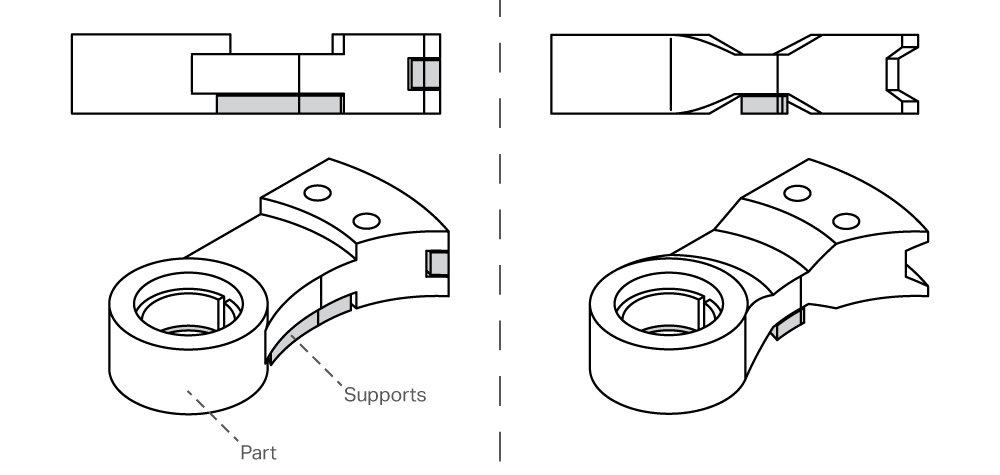
Since a printer cannot extrude plastic into thin air without it collapsing, all parts of each layer must be connected to the layer below. While this is implicitly true for some parts, others have overhangs that require supports. Supports are an automatically generated sacrificial scaffold that come in a few different forms: peel away supports made from the same material as the part, soluble supports that dissolve in a bath after printing, or release layer supports that build a scaffold of part material with an intermediary layer of release material in-between the part and the support structure. Printers with a secondary material for supports use a second nozzle on the print head specifically for support material.
The layer-by-layer nature of the 3D printing process causes 3D printed parts exhibit transverse isotropic material properties. While isotropic materials have uniform material properties in all directions, transverse isotropic materials have one set of properties along an axis and a different set on planes normal to that axis. This translates to 3D printed parts, which exhibit higher part strength on XY planes talong the Z axis. This is why it’s important to consider print orientation during the design process.
The basics of infill
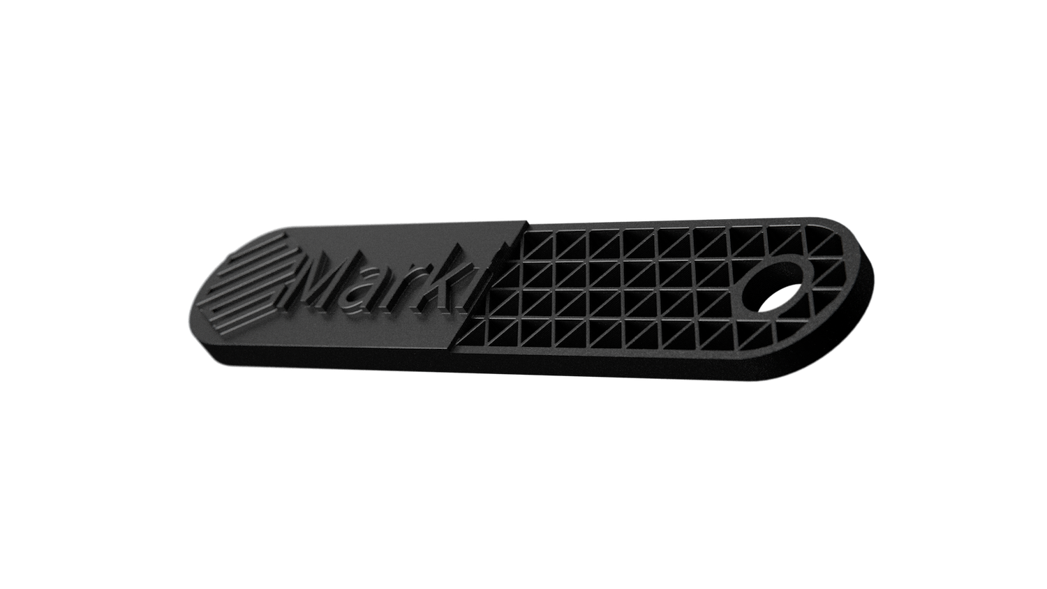
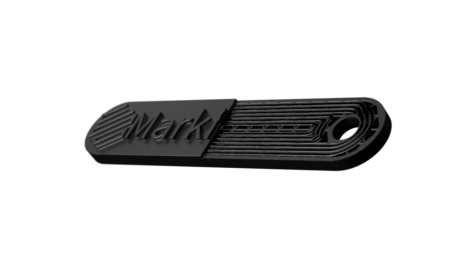
While the shell of a part defines its shape and accuracy, infill is incredibly important in determining its performance. Infill is optimized for strength and print quality, and is always made up of a tessellating shape distributed over the area of a layer. Typically, triangles are used because of their perfect load distribution, but other shapes can be used as well. Altering the shape and density of the infill changes the mass and (to a lesser degree) the strength of your part. Infill orientation is governed by the print orientation, so if you want infill in a certain direction you’ll need to plan for it when you first orient the part.
Continuous fiber reinforcement replaces conventional infill in select geometries, significantly improving mechanical properties. On certain layers, you can substitute the normal infill of a part with automatically routed continuous fibers. The strength increase these fibers provide depends on the print orientation, how much continuous fiber you add to the part, where continuous fiber is added, and what fiber you choose to add.
Print time and material
Print time is largely defined by how many paths of material the printer needs to draw out on every layer. First, infill prints very quickly and shells print very slowly. Second, supports print very slowly, as they have massive surface area. All these factors add up to the total time it takes to print a given part. As a result, surface area, supports, and volume are equally important in determining print time. Since part volume can be hard to control based on the size of a part, try to minimize surface area and supports to reduce print time.
Printer material estimates are accurate and easy to calculate with 3D printing, because a printer knows how much material it uses when it extrudes a toolpath. Just like calculating print time, a similar rule applies to material consumption—the more surface area and supports you have, the more material is going to be used. Support material can account for a significant part of material usage, so minimizing supports can decrease material usage for an equal size part.
3D printing accuracy and build size
3D printing accuracy depends on a number of factors, including material, print settings, and part orientation. However, there are a few things you can do to maximize accuracy:
Print with default settings: Most industrial-grade printers optimize their accuracy for prints using base settings.
Print features requiring high accuracy in the XY plane: Since the XY gantry is a unified motion system, printers produce far more accurate geometries on the XY (horizontal) than the XZ or YZ (vertical) planes. Try to design or orient your part such that holes and other critical features lay flat on the print bed.
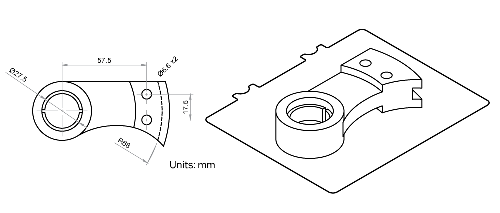
Reduce supports and overhangs: Supports ensure that geometrically complex prints are successful; however, they also mar the supported surface and yield significantly less accurate features than sections that do not require support.
Build Volume: Printer size is defined by its build volume—the maximum range of the gantry and Z motion system. However, that doesn’t mean that you should try to fill the entire volume with a single part. 3D printing is the opposite of subtractive manufacturing, in which you start from a block of raw stock and try to remove as little material as possible. As a result, large and blocky parts often are cheaper and faster to fabricate with other methods.

Written by Markforged
Markforged is transforming manufacturing by addressing 3D printing as a holistic problem. Their process innovations are only possible by a combined effort in advanced cloud computing, cutting-edge materials science, and industrial design.

